
Smart Home Control Panel Displays — CTP Size Range
Wall-mounted smart home hubs and thermostat panels want flush black-glass fronts and always-on clarity. RONEN supplies 27 capacitive modules from 4.3″ to 10.1″ at 480x272–1280x800 resolution with full-flat bonding options and stable backlights for 24/7 panels. ODM covers black cover lens, silk-print bezels and custom touch tuning.
- 27 CTP modules 4.3″–10.1″ for flush wall panels
- Full-flat black cover lens + bonding via ODM
- 24/7 duty: stable backlight, 250–1000 cd/m² range
A Wall Panel Is a Glass Problem Before It Is a Display Problem
What a homeowner judges is the front: a single black sheet, flush with the wall, with no visible border and no gap where dust collects. That look constrains the electronics more than the UI does. The panel sits behind 0.7–2 mm of cover glass with a printed black border, and the border has to align with the active area to within a fraction of a millimetre or the edge looks uneven under a downlight.
Three mechanical decisions follow, and all three should be settled before the industrial design is frozen:
- Border width. A printed border hides the module’s bezel and the FPC bend. Narrowing the border by 2 mm can force a different FPC exit edge, which changes the whole layout.
- Stack height. Panel plus backlight plus bonding plus glass is the wall protrusion. Every 0.5 mm counts in a flush-mount box with a 35 mm cavity depth.
- Service access. A bonded front cannot be opened; the electronics have to come out of the back. That is a different rear housing, not a different panel.
Full Lamination vs Air Gap
An air gap between the panel and the cover glass is the cheap route, and it is visible in three ways: a double reflection when a lamp is behind the viewer, a slight haze over dark UI because light scatters inside the cavity, and dust that creeps in from the edge over the product’s life. On a black home-automation panel, all three read as “cheap” within a metre.
Full lamination with an optical adhesive removes the cavity: one reflection instead of two, no dust path, and a black that stays black. It costs a bonding step and makes the panel non-serviceable as a separate part. For a wall panel that is normally the right trade — the failure that actually occurs is the touch controller or the backlight, and both are replaced as an assembly anyway.
Touch Through 3 mm of Glass
A capacitive sensor behind a thick decorative glass loses signal at the same rate the glass gains ruggedness. Two thresholds matter. Up to roughly 1.5 mm of additional glass the standard tuning normally holds; between 1.5 and 3 mm the controller has to be tuned against the final stack, and the firmware must be fixed before certification because retuning changes the reported coordinates slightly. Beyond about 3 mm, expect a sensor redesign rather than a tuning change.
Wake-on-touch is a separate problem. A panel that must wake from a dark screen cannot poll at full rate all night; the usual arrangement is a low-power scan at a few hertz that raises an interrupt on the first contact, then switches to 100 Hz. Tune that first-contact threshold on the real glass, with a dry finger and with a slightly damp one — kitchen and bathroom panels get both.
Always-On Panels: Dimming Curves and Sticking
An always-on panel spends most of its life showing the same layout: a temperature, a mode icon, a status bar. That is the recipe for residual image, and the fix is mostly in the dimming curve. At night the panel should fall to somewhere around 5–15 cd/m² — bright enough to read across a dark bedroom, dim enough not to light the wall — and the UI should shift to a dark theme rather than dimming a white one, because a dimmed white screen is still a full-white field.
Flicker is the second issue. PWM dimming at a few hundred hertz is visible as banding when a phone camera looks at the panel, and some people perceive it directly at low brightness. Above about 2 kHz, or with analogue dimming, the panel photographs cleanly — worth specifying if the product will appear in user photos and reviews.
Relays, Motors and Wi-Fi Inside the Wall Box
A smart-home panel shares its cavity with relay boards, a triac dimmer or a motorised valve. When a relay drops out, the resulting transient can shift the touch baseline and register a phantom press on the nearest key — typically the one under the relay’s own icon. This is a layout problem before it is a firmware problem: keep the touch FPC away from the mains switching node, keep the mains and the logic grounds separate until a single star point, and give the controller a re-calibration window after each switching event.
The 2.4 GHz radio is a milder neighbour, but an antenna placed directly behind the panel is shielded by the panel’s own ground plane. If the enclosure leaves no other place for the antenna, expect a range penalty and test it in the actual wall box, not on a bench.
The Range at a Glance
Twenty-seven capacitive modules across five diagonals. The 800×480 group is the volume choice for a wall panel read at 50–70 cm; 1024×600 is worth the step up when the UI shows a floor plan or a camera feed.
| Size | Models | Resolutions in this range | Panel / touch variants | Where it usually goes |
|---|---|---|---|---|
| 4.3″ | 5 | 480×272, 800×480 | IPS 4 / TN 1 | Thermostat, room controller |
| 5.0″ | 5 | 800×480 | IPS 4 / TN 1 | Compact wall panel |
| 7.0″ | 12 | 800×480, 1024×600 | TN 9 / IPS 3 | Standard wall panel |
| 8.0″ | 1 | 1024×768 | IPS 1 | Large wall panel |
| 10.1″ | 4 | 1024×600, 1280×800 | IPS 4 | Central control panel |
Standard Modules in This Range
27 standard models in this family
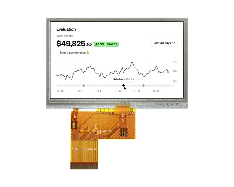
RG-T043QPS-02CA
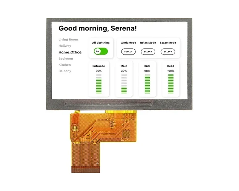
RG-T043BPSA-01CA
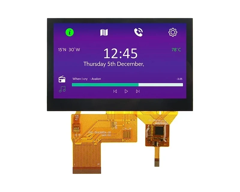
RG-T043BPSA-02CP
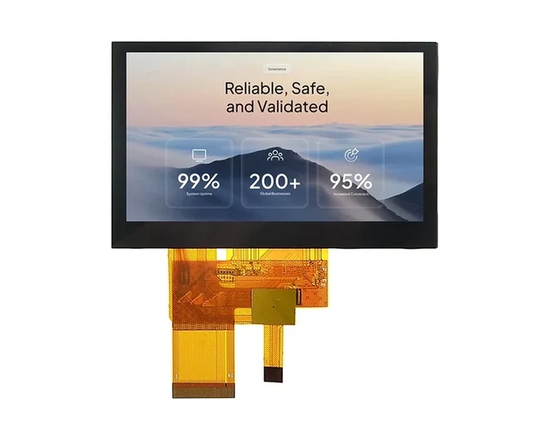
RG-T043BWSA-02CP
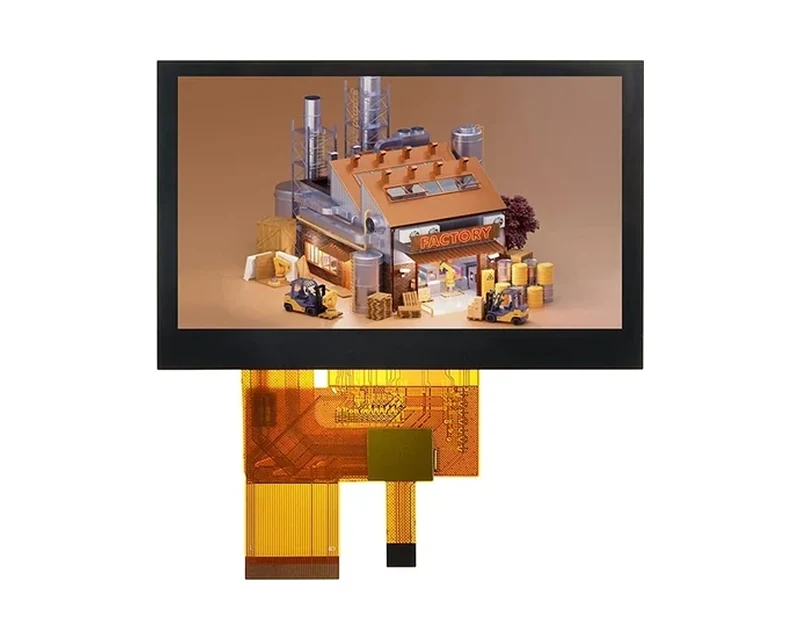
RG-T043BWSA-28CP
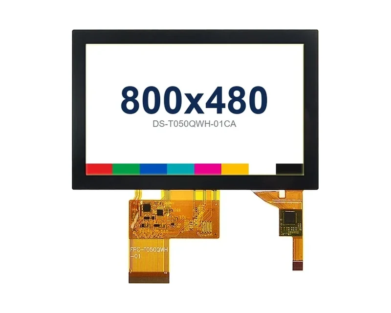
RG-T050QWH-01CA
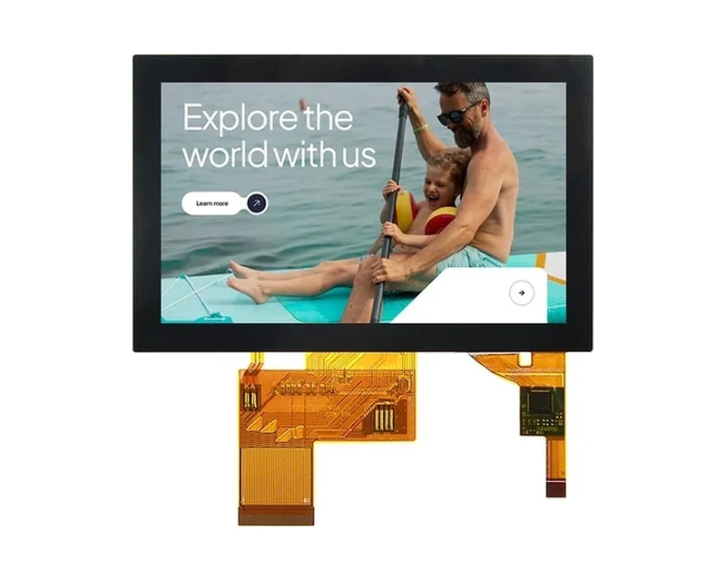
RG-T050BWSA-30CP
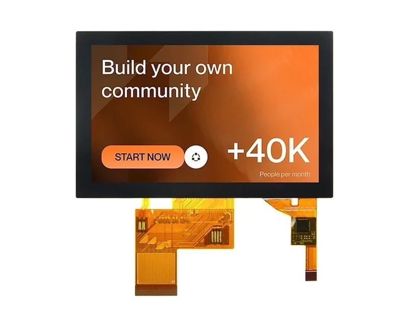
RG-T050BWSA-02CP

RG-T050BWSWA-02CP

RG-T050BWSWA-02CA
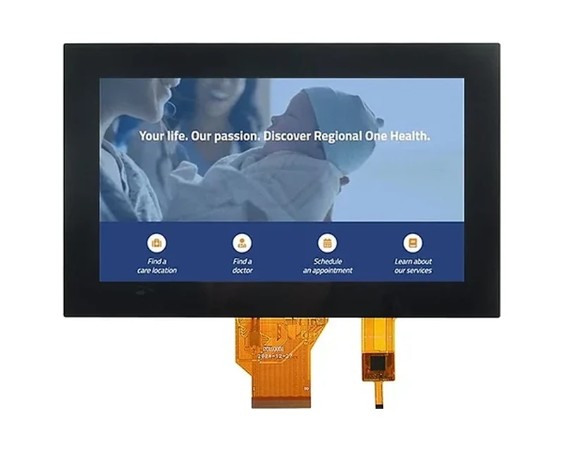
RG-T070QWE-01AD
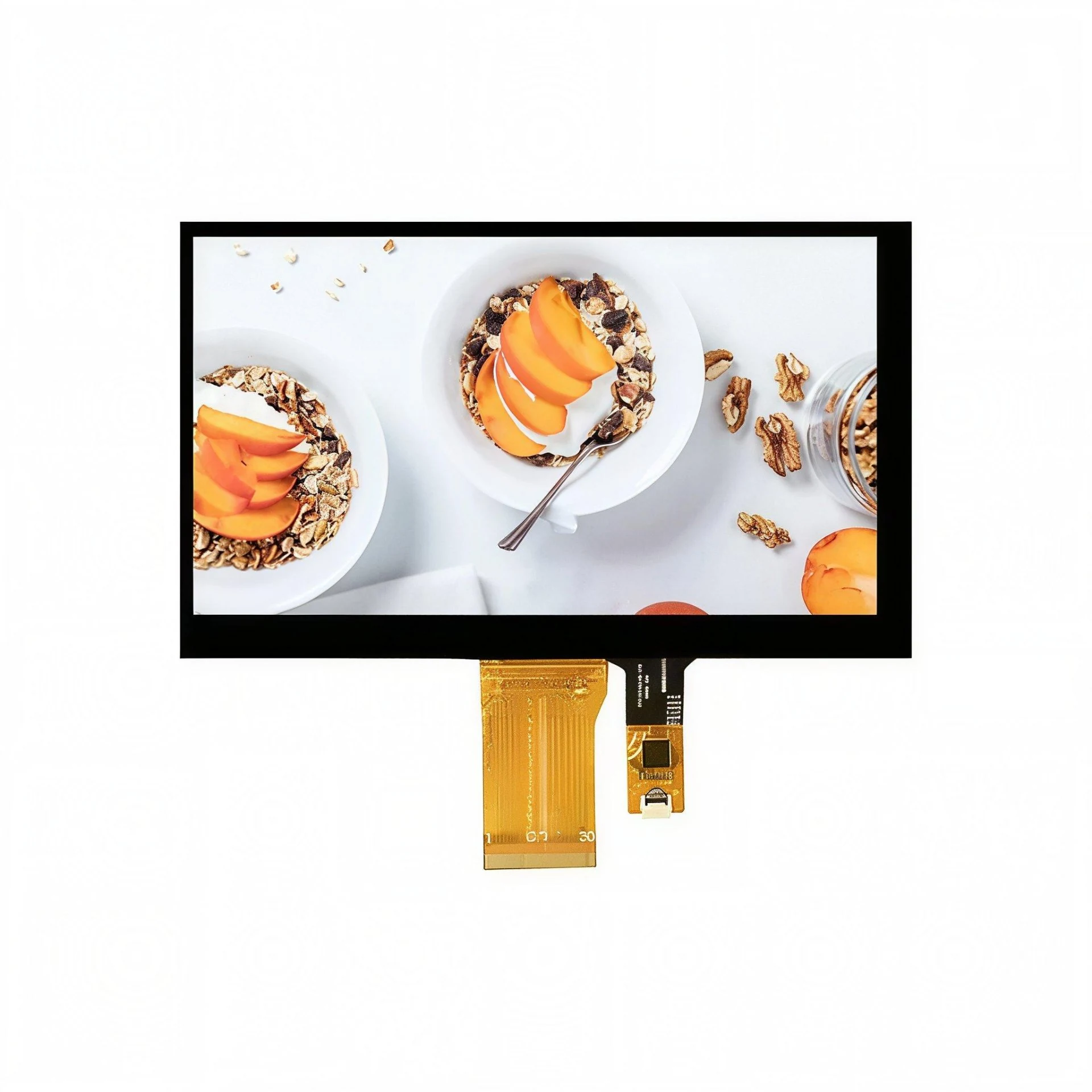
RG-T070QWHW-01CA
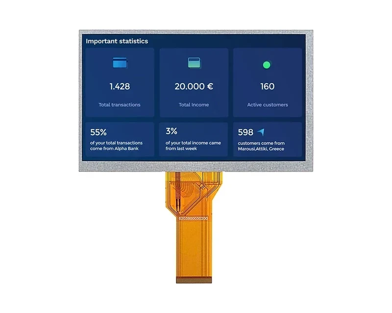
RG-T070QWHW-02
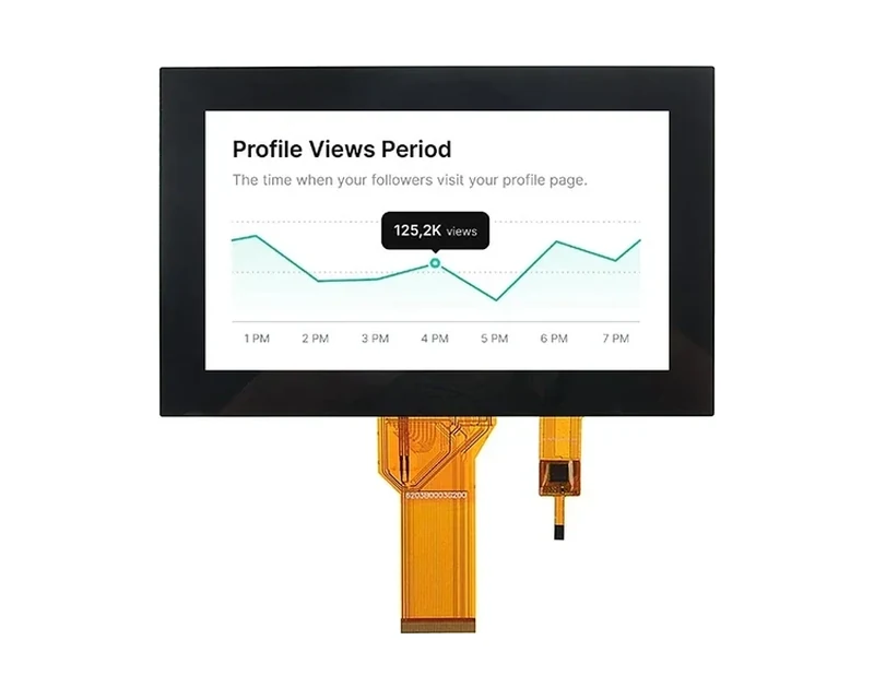
RG-T070QWHW-02CA
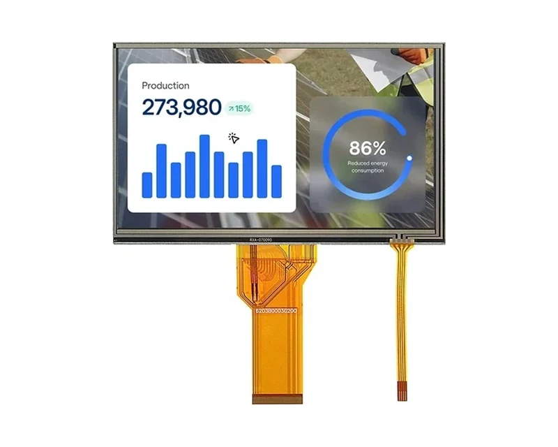
RG-T070QWHW-03CA
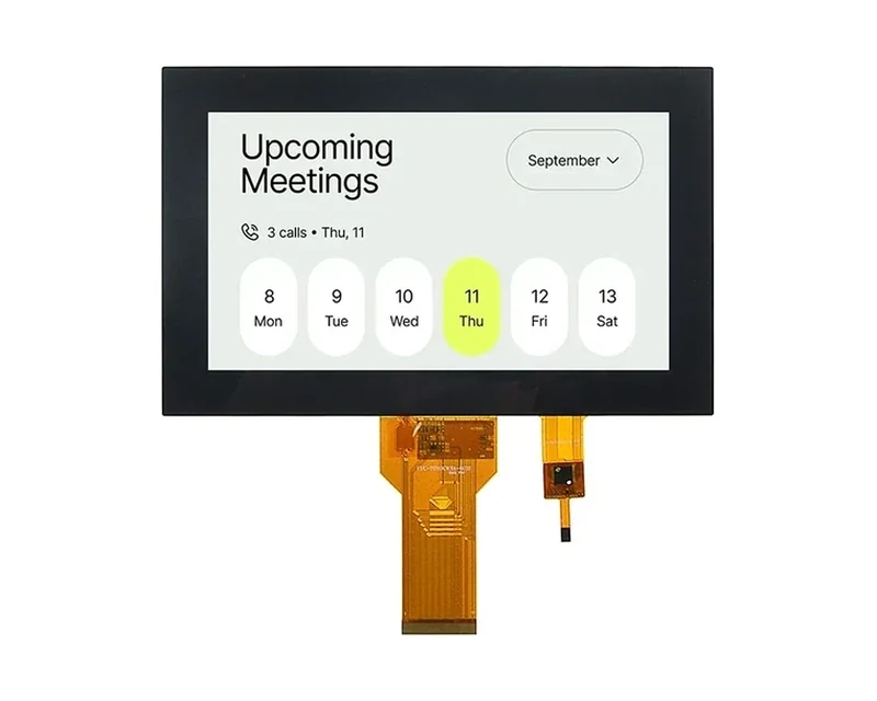
RG-T070KWSA-01CA
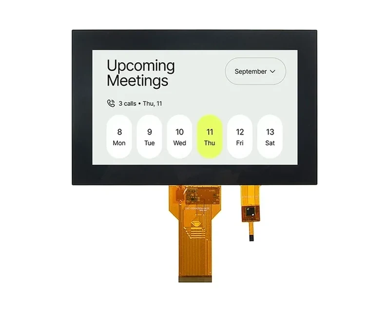
RG-T070KWSA-01CP
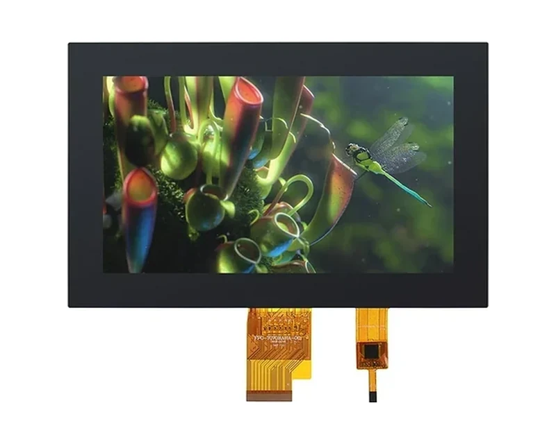
RG-T070BAHA-01CA
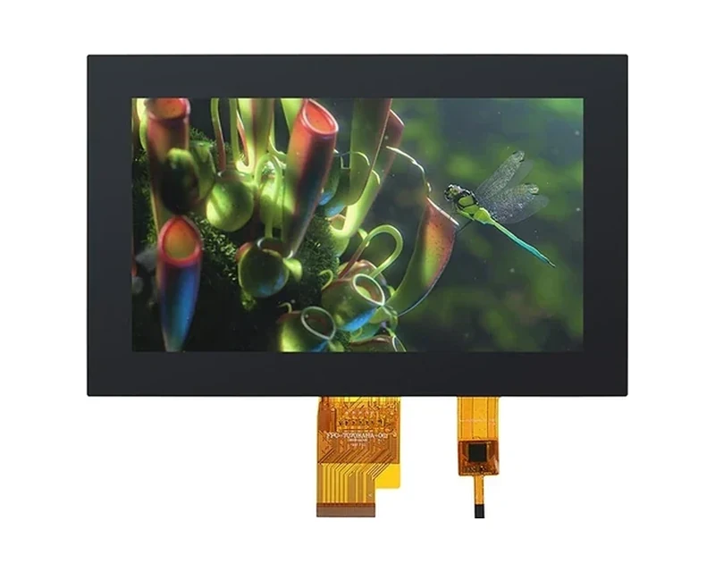
RG-T070BAHA-01CP
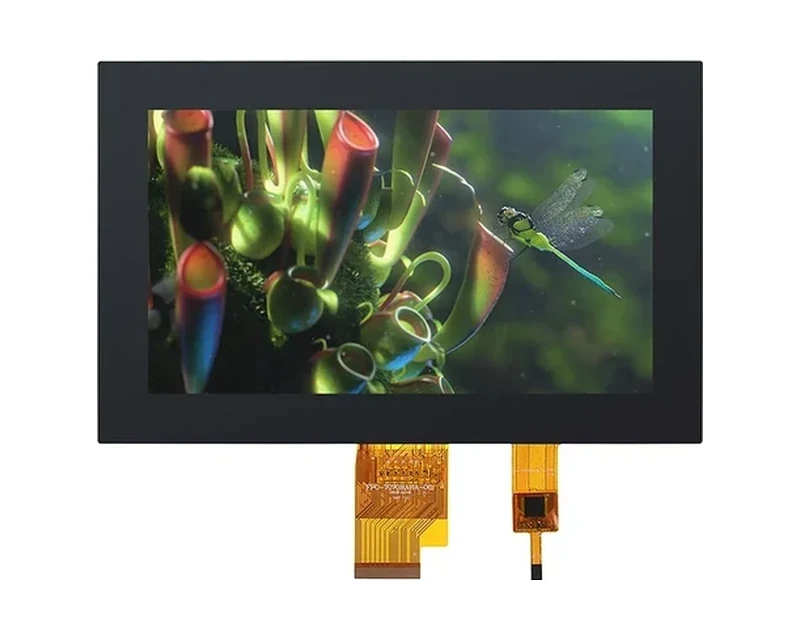
RG-T070BAHA-03CA
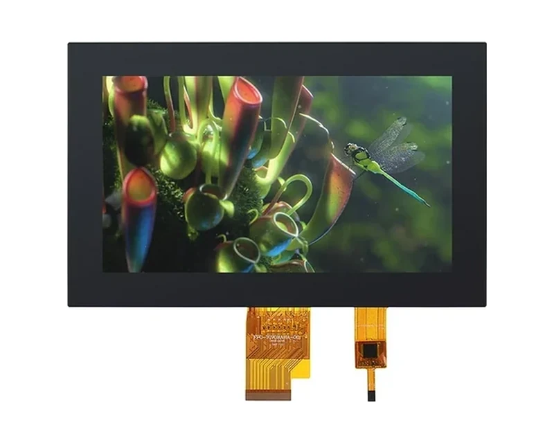
RG-T070BAHA-03CP
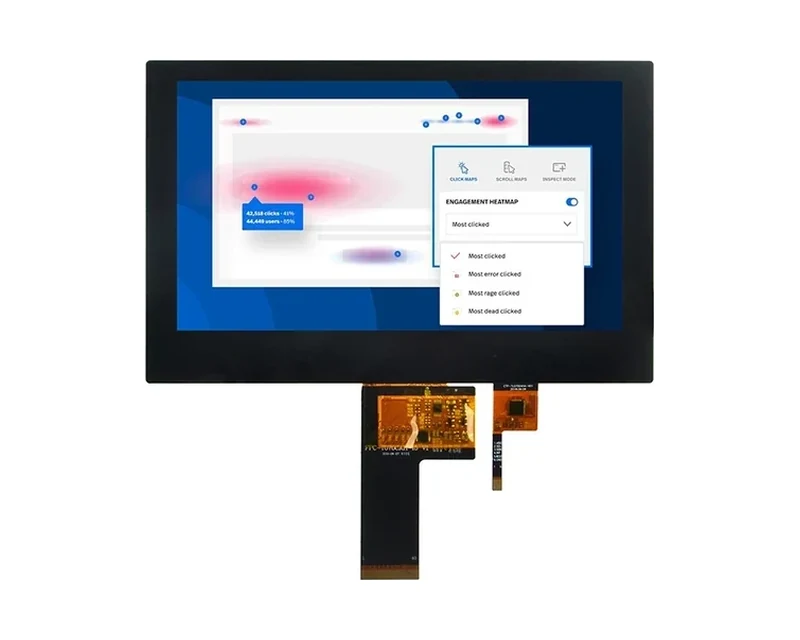
RG-T070BAHA-19CA
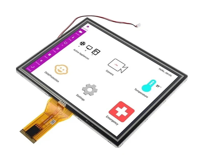
RG-T080BXEA-01CP

RG-T101BAHA-02CP
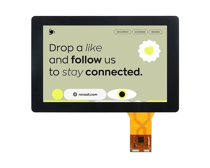
RG-T101HIEWA-01CP
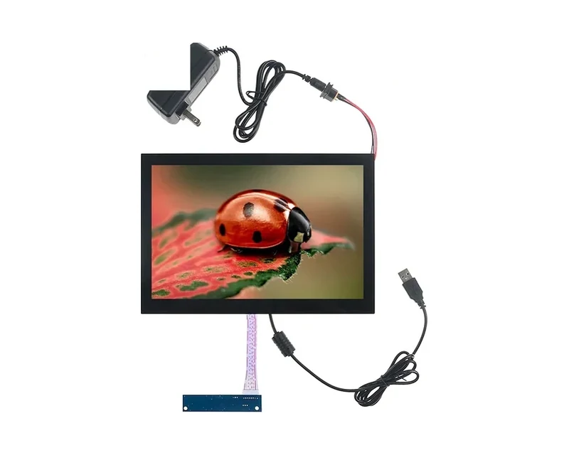
RG-T101QIHA-01CA-B
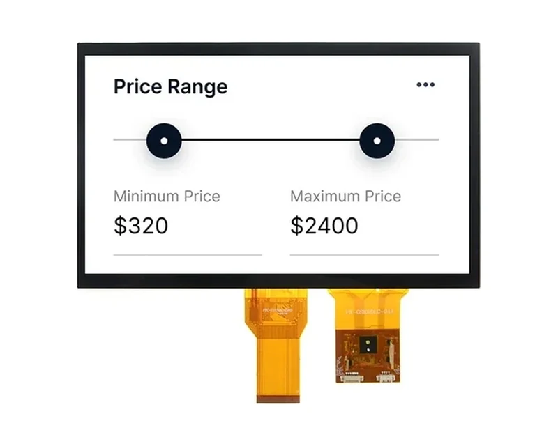
RG-T101BAHA-02CD
Can’t find the exact model you need?
This is a standard model, and our online catalog shows only part of what we build. We hold additional models not listed here, and we can adjust brightness, interface, touch or outline within an existing product family, or evaluate a fully custom solution. If this model does not fully match your requirements, please email your specifications to sales@odmlcd.com. We’ll help you identify the right part or assess a custom option.
FAQ
Is the touch responsive?
Our PCAP line (36 standard models) supports 10-point multi-touch, glove and wet-hand operation, with ≥100 Hz sampling rate. Controllers are selected for industrial EMI environments and can be tuned for the thickness / cover-lens stack-up.
Can you support standard supply and development?
Yes. Our 70+-engineer R&D team takes requirements from concept to EVT; for shaped / odd-form displays the concept-to-EVT cycle is 6–8 weeks with NRE from quoted per project depending on structural complexity. FPC, backlight, cover-lens, bonding and interface are all customizable.
What are the order quantities and stock?
All 190+ standard models are held in our standard program, so you can order exactly the quantity your build needs, from prototype runs to volume production. Custom / ODM builds are quoted case by case (typically 10–500 pcs) with volume-based pricing — tell us your volume and we'll quote.
Can you supply the black cover glass as part of the module?
Yes, as an ODM assembly. The glass is printed, strengthened and optically bonded to the panel, and the module arrives as one part with the touch already tuned for that stack. Send the outline drawing, glass thickness, print artwork and the intended bonding method; the active-area position and FPC keep-out are then fixed together rather than designed around each other.
Does a thicker cover glass reduce touch sensitivity?
It reduces signal-to-noise, and the controller tuning compensates up to a point. Up to about 1.5 mm of added glass the standard tuning usually holds; between 1.5 and 3 mm the stack must be tuned as a unit; beyond 3 mm the sensor itself is usually redesigned. The threshold depends on the sensor pattern and the controller, so the glass thickness belongs in the first technical conversation, not the last.
How dim can the panel go at night?
Most modules in this range dim to roughly 5–15 cd/m², which is comfortable in a dark room without lighting the wall. Below that, PWM artefacts and colour shift become visible. The practical approach is a dark-theme UI at low luminance rather than a dimmed white screen: a dimmed full-white field still emits across the whole panel area and still ages the backlight.
Will the display interfere with the home’s wireless?
The panel itself does not radiate, but its ground plane shields whatever sits behind it. An antenna placed directly behind the module will lose range, and a metal backlight housing makes that worse. Keep the radio at the edge of the board or in a separate cavity, and verify range in the installed wall box rather than on a bench.
What happens when a relay in the same box switches?
A switching transient can shift the capacitive baseline and register a false touch, usually on the key nearest the relay. Mitigate in layout first — separation, separate grounds joined at one star point, a snubber across the relay coil — and in firmware second, with a re-calibration window after each switching event.