
Railway Display Modules — Wide Temperature & Vibration-Ready TFT | RONEN
Rolling stock and trackside cabinets combine vibration, condensation, −30 °C winters and 24/7 operation. RONEN supplies 33 railway-suitable TFT modules, 29 of them rated −30 to +80/+85 °C, with high-brightness options for cab displays, door indicators, passenger information systems and trackside HMI — with 5+ year supply continuity for long vehicle programs.
- 29 of 33 standard modules rated −30 °C to +80 / +85 °C — the other four are compact in-cab parts
- High brightness up to 1500 cd/m² for sunlight-exposed cab and door positions
- Railway-grade design practices: vibration-tolerant mounting, conformal coating options
- Long-term supply continuity — spares and pin-compatible successors for 5+ years
What a Railway Installation Actually Asks of a Display
Rail equipment is not simply industrial equipment that moves. It combines a narrow ambient window, a service life measured in decades and a maintenance cycle counted in overhauls rather than years. Four conditions account for most in-service display failures, and each one maps to a different line on the datasheet than the one buyers usually check first.
- Cold start, not just cold running. A cab display that sits overnight at −25 °C has to show a readable image within seconds of power-up. Liquid-crystal response time rises steeply as temperature falls, so a module rated to −30 °C can still look sluggish for the first minutes after a winter start. Programs that care about this specify the low-temperature response figure and, where the enclosure allows it, a heater film behind the panel.
- Condensation on every tunnel exit. Warm humid air meets a cold front glass and water films the inside of the window. A sealed module with desiccant or a breathable membrane vents the cavity; a conformal coating protects the driver board when the seal is imperfect. Neither appears on a brightness specification, and either one decides whether a unit survives its first winter.
- Continuous operation at high brightness. Passenger information strips and door indicators run around the clock for the life of the vehicle. A 1000 cd/m² backlight driven at full current loses output faster than a 700 cd/m² unit run at the same fraction of its rating. Specify the luminance you need after five years, not the luminance on day one.
- Vibration and shock at the mounting interface. The glass rarely fails first — the FPC tail, the connector latch and the bezel fixings do. Locking connectors, strain relief on the tail and thread-locking compound on the screws matter more than a rugged-looking front bezel.
Vehicle programs usually express these requirements through EN 50155 (ambient temperature classes, supply-voltage ranges and disturbance tests) and EN 45545 (fire performance of materials), with EN 61373 covering vibration and shock for equipment mounted on the body or the bogie. Those documents define what the finished equipment must survive; the display is one component inside that envelope and the system integrator holds the type approval. What a display supplier can do is supply modules whose ratings leave margin against the class you are qualifying to, together with the drawings and test evidence your qualification file needs.
Matching the Module to the Position on the Vehicle
One train uses very different displays in different places, and collapsing them into a single requirement is the most common specification error. A door indicator and a driver's desk monitor do not share a brightness target, a touch requirement or a viewing distance.
| Position | Typical size | Luminance target | Touch | What decides the choice |
|---|---|---|---|---|
| Driver's desk and cab auxiliary display | 7.0″–12.1″ | 500–1000 cd/m² | Usually none, or resistive for gloved use | Legibility against low sun through the windscreen; shallow depth behind the desk; long cable runs favour LVDS |
| Door open / close indicator | 2.8″–4.3″ | 700–1200 cd/m² | None | Brightness at a shallow viewing angle; must stay readable through a tinted or dusty window; vibration at the door mechanism |
| Passenger information strip and saloon panel | 10.1″–18.5″ | 700–1000 cd/m² | None | 24/7 duty, luminance decay across the overhaul interval, wide viewing angle along the saloon |
| Trackside cabinet HMI | 5.0″–10.1″ | 500–1000 cd/m² | Capacitive with gloves, or resistive | Unheated cabinet from −30 °C to +70 °C; direct sun on the cabinet face in summer; condensation on cold mornings |
| Ticket machine and station kiosk | 7.0″–15.6″ | 700–1000 cd/m² | Capacitive, often behind anti-vandal glass | Public use, cleaning chemicals, sun-exposed concourse |
The range below covers that table from 2.8″ to 18.5″. Twenty-nine of the 33 modules are rated from −30 °C. The four exceptions — three compact parts at −20 to +70 °C and one 12.1″ part at −30 to +70 °C — suit in-cab positions where the vehicle heating keeps the enclosure above freezing, and are called out in the matrix rather than averaged into a headline number.
The Standard Range, by Specification
Every line below is a catalogue part with a published datasheet, not a build-to-order placeholder. Sizes run from 2.8″ to 18.5″, luminance from 250 to 1500 cd/m², and all five interface families used on rolling stock — RGB parallel, RGB/MCU/SPI, LVDS single channel, LVDS dual channel and MIPI DSI — appear at least once. Nine modules ship with a capacitive touch panel bonded, two with resistive.
| Part number | Size | Resolution | Panel | Luminance | Interface | Operating temp. | Touch |
|---|---|---|---|---|---|---|---|
| RG-T028GQSW-01 | 2.8″ | 240x320 | TN | 350 cd/m² | RGB / MCU / SPI | −30 to +80 | — |
| RG-T028BQSWA-01 | 2.8″ | 240x320 | IPS | 350 cd/m² | RGB / MCU / SPI | −30 to +85 | — |
| RG-T034BOIA-01 | 3.4″ | 800x800 | IPS Round | 1000 cd/m² | MIPI DSI, 4-lane | −20 to +70 | — |
| RG-T0345BHSA-01 | 3.45″ | 340x800 | IPS Bar | 400 cd/m² | RGB 18-bit, 40-pin | −20 to +70 | — |
| RG-T035HLWSA-01 | 3.5″ | 320x240 | IPS | 900 cd/m² | RGB 24-bit, 54-pin | −30 to +85 | — |
| RG-T035HLSWA-01 | 3.5″ | 320x240 | IPS | 1200 cd/m² | RGB 24-bit | −30 to +85 | — |
| RG-T043BPSWA-02 | 4.3″ | 480x272 | IPS | 700 cd/m² | RGB 24-bit | −30 to +80 | — |
| RG-T043BWSWA-02 | 4.3″ | 800x480 | IPS | 900 cd/m² | RGB 24-bit | −30 to +80 | — |
| RG-T050BWSWA-02 | 5.0″ | 800x480 | IPS | 1000 cd/m² | RGB 24-bit, 40-pin | −30 to +80 | — |
| RG-T050BWSWA-02CP | 5.0″ | 800x480 | IPS | 850 cd/m² | RGB 24-bit, 40-pin | −30 to +80 | CTP |
| RG-T050BWSWA-02CA | 5.0″ | 800x480 | IPS | 850 cd/m² | RGB 24-bit | −30 to +80 | CTP |
| RG-T070QWHW-01 | 7.0″ | 800x480 | TN | 550 cd/m² | RGB 24-bit, 50-pin | −30 to +85 | — |
| RG-T070QWHW-01P | 7.0″ | 800x480 | TN | 480 cd/m² | RGB 24-bit, 50-pin | −30 to +85 | RTP |
| RG-T070QWHW-01CA | 7.0″ | 800x480 | TN | 500 cd/m² | RGB 24-bit, 50-pin | −30 to +85 | CTP |
| RG-T070QWHW-02 | 7.0″ | 800x480 | TN | 1000 cd/m² | RGB 24-bit, 50-pin | −30 to +85 | CTP |
| RG-T070QWHW-02P | 7.0″ | 800x480 | TN | 850 cd/m² | RGB 24-bit, 50-pin | −30 to +85 | RTP |
| RG-T070QWHW-02CA | 7.0″ | 800x480 | TN | 850 cd/m² | RGB 24-bit, 50-pin | −30 to +85 | CTP |
| RG-T070QWHW-03CA | 7.0″ | 800x480 | TN | 400 cd/m² | RGB 24-bit, 50-pin | −30 to +85 | CTP |
| RG-T070SWHWA-01 | 7.0″ | 800x480 | IPS | 1000 cd/m² | LVDS 6/8-bit, 20-pin | −30 to +85 | — |
| RG-T070SWHWA-02 | 7.0″ | 800x480 | IPS | 500 cd/m² | LVDS 6/8-bit, 20-pin | −30 to +85 | — |
| RG-T080BXEWA-01 | 8.0″ | 1024x768 | IPS | 300 cd/m² | LVDS 6/8-bit, 40-pin | −30 to +80 | — |
| RG-T080BXEA-01CP | 8.0″ | 1024x768 | IPS | 250 cd/m² | LVDS 6/8-bit, 40-pin | −30 to +80 | CTP |
| RG-T084BXJWA-01 | 8.4″ | 1024x768 | TN | 500 cd/m² | LVDS | −30 to +80 | — |
| RG-T101BYEA-01ND | 10.1″ | 800x1280 | IPS | 300 cd/m² | MIPI DSI, 4-lane | −20 to +70 | — |
| RG-T101HIEWA-01 | 10.1″ | 1280x800 | IPS | 1000 cd/m² | LVDS 6/8-bit, 40-pin | −30 to +85 | — |
| RG-T101HIEWA-01CP | 10.1″ | 1280x800 | IPS | 850 cd/m² | LVDS 6/8-bit, 40-pin | −30 to +85 | CTP |
| RG-T101HIEWA-03 | 10.1″ | 1280x800 | IPS | 1000 cd/m² | LVDS 6/8-bit, 40-pin | −30 to +80 | — |
| RG-T101HIEWA-04 | 10.1″ | 1280x800 | IPS | 500 cd/m² | LVDS 6/8-bit, 40-pin | −30 to +80 | — |
| RG-T121QXHA-02 | 12.1″ | 1024x768 | IPS | 600 cd/m² | LVDS 6/8-bit, 30-pin | −30 to +70 | — |
| RG-T156QFHWA-01 | 15.6″ | 1920x1080 | IPS | 1000 cd/m² | LVDS 2-ch 8-bit, 40-pin | −30 to +85 | — |
| RG-T156BFHWA-02 | 15.6″ | 1920x1080 | IPS | 1000 cd/m² | LVDS 2-ch 8-bit | −30 to +80 | — |
| RG-T156BFHWA-02CP | 15.6″ | 1920x1080 | IPS | 850 cd/m² | — | −30 to +80 | CTP |
| RG-T185BFHWA-02 | 18.5″ | 1920x1080 | IPS | 1500 cd/m² | LVDS 2-ch 8-bit, 30-pin | −30 to +80 | — |
Where a position needs a brightness, interface, touch construction or outline that is not in this list, the same panel family can usually be re-built around it — a different backlight stack for higher luminance, a bonded CTP, a longer FPC or a different connector. Send the position and the environmental envelope, and the nearest catalogue part plus the delta is a faster starting point than a blank sheet.
Where Railway Display Specifications Usually Fail
Field returns on rail displays cluster around five mechanisms. Each has a specification line that predicts it, and a design measure that prevents it — and the two are rarely the same line.
| Failure mode | What actually happens | Line to check | Design measure |
|---|---|---|---|
| Slow or blank image at cold start | Response time and contrast collapse below −20 °C; some drivers fail to lock at low temperature | Operating temperature and the low-temperature response figure | Wide-temperature liquid crystal, heater film, driver IC rated for the low end |
| Fogging behind the cover glass | Moisture migrates into the air gap and condenses on the inside of the window | Bonding method (air gap vs. optical bonding) and IP rating | Optical bonding to remove the air gap, desiccant or breathable vent, conformal coating on the PCB |
| Progressive dimming after 2–3 years | LED output falls faster than expected because the backlight ran near its rated current at elevated temperature | Luminance at day one vs. luminance required at end of life; backlight drive margin | Specify end-of-life luminance, run the backlight derated, keep panel temperature down |
| Intermittent image, then dead column | The FPC tail fatigues or the connector latch releases under vibration | Connector type, tail length and fixing method | Locking connector, strain relief, tail support, thread-locking compound on fixings |
| Panel overheats in direct sun | A dark bezel in summer sun pushes the panel above its rated storage or operating limit | Operating and storage temperature vs. measured surface temperature in the enclosure | Ventilated bezel, lighter colour, thermal path to the chassis, brightness chosen for the real ambient rather than the worst case imaginable |
The pattern behind all five: the datasheet maximum is a limit, not a target. A module rated to +85 °C run continuously at +80 °C will not deliver its rated backlight life, and a 1500 cd/m² part is the wrong choice for a shaded cab if the extra heat has to be removed from a sealed enclosure.
Interface Choice Over a 15-Year Program
The interface is the decision most likely to be regretted, because it is the one that ties the display to a processor generation. Rail electronics are typically supported for a decade or more, well past the life of the SoC that was current when the design started.
| Interface | Practical cable run | Typical use here | Watch out for |
|---|---|---|---|
| RGB parallel (18 / 24-bit) | Short — tens of centimetres | 2.8″–7.0″ in-cab and door indicators | Wide ribbon with many conductors; EMI rises with length; pin count grows with colour depth |
| RGB / MCU / SPI combo | Short | Small panels where the host drives the display directly | Mode switching on the same connector; check the host actually supports the mode you want |
| LVDS, single and dual channel | Metres, on shielded twisted pairs | 7.0″–18.5″ PIS, cab monitors, trackside HMI | Pair skew and connector pinout vary between panel makers — the cable is part of the design, not an accessory |
| MIPI DSI | Short, and sensitive to routing | Compact high-resolution parts, 3.4″ and 10.1″ here | Fewer lanes mean lower bandwidth; long or poorly matched traces show up as dropped frames |
Across the 33 modules the split is 17 RGB, 13 LVDS and 2 MIPI DSI, with one bonded-touch variant whose interface is defined by its base part. That distribution is deliberate: the further the display sits from the controller, the more likely LVDS is the right answer, and a program that expects a ten-year hardware life should avoid putting a short-run parallel interface at the end of a two-metre harness.
Supply Continuity Across an Overhaul Interval
A passenger vehicle is expected to run for 25 to 30 years, and its displays are replaced on the overhaul cycle rather than with the vehicle. That turns the sourcing question from “can you supply this today” into “will this part, or something that drops into its place, still exist in eight years”. Three things make the difference: the module is a catalogue part produced continuously rather than a project build, the supplier commits to a pin-compatible successor when a panel or driver IC is revised, and change notification arrives early enough to re-qualify before the old part disappears.
RONEN keeps the wide-temperature range as catalogue product with published change-notification and last-time-buy terms rather than as a made-to-order line, and supports replacement modules that keep the outline, mounting holes and interface of the part they supersede. For a program with a ten-year horizon the practical step is to name a primary and a second source in the qualification file at design time, while both are still available — not after the first PCN arrives.
33 Standard Modules Rated for Railway Environments
33 wide-temperature standard models suitable for railway applications
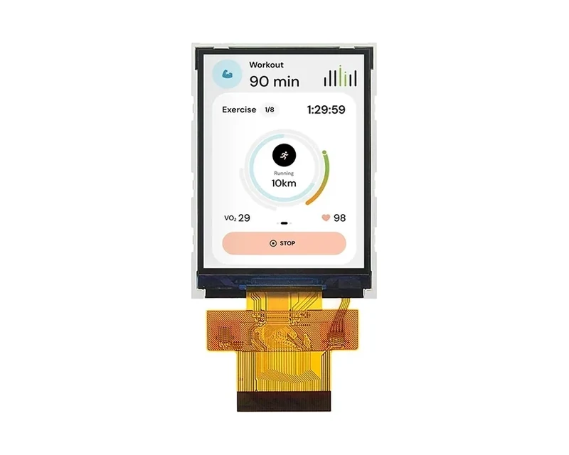
RG-T028GQSW-01
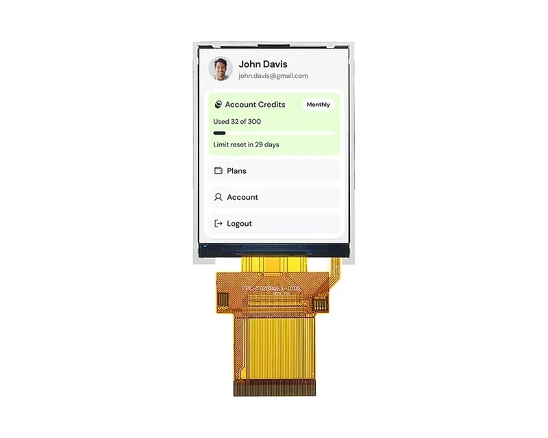
RG-T028BQSWA-01
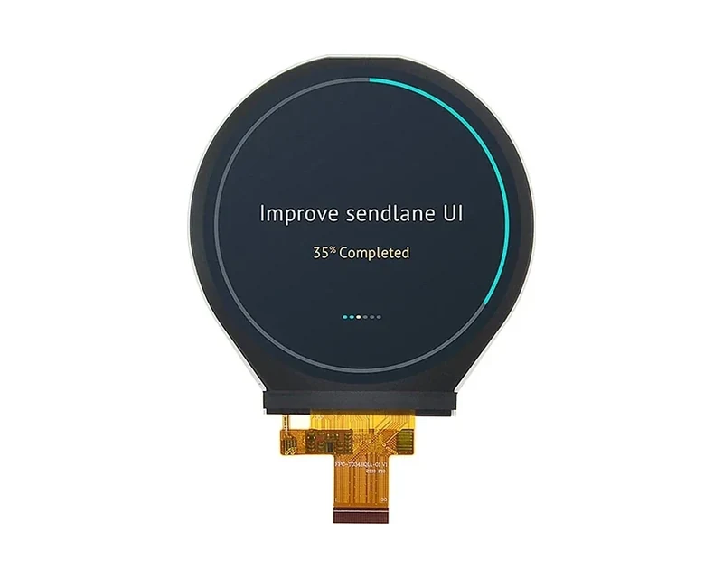
RG-T034BOIA-01
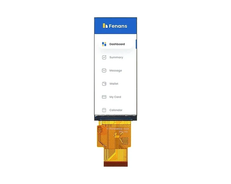
RG-T0345BHSA-01
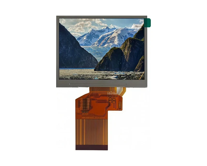
RG-T035HLWSA-01
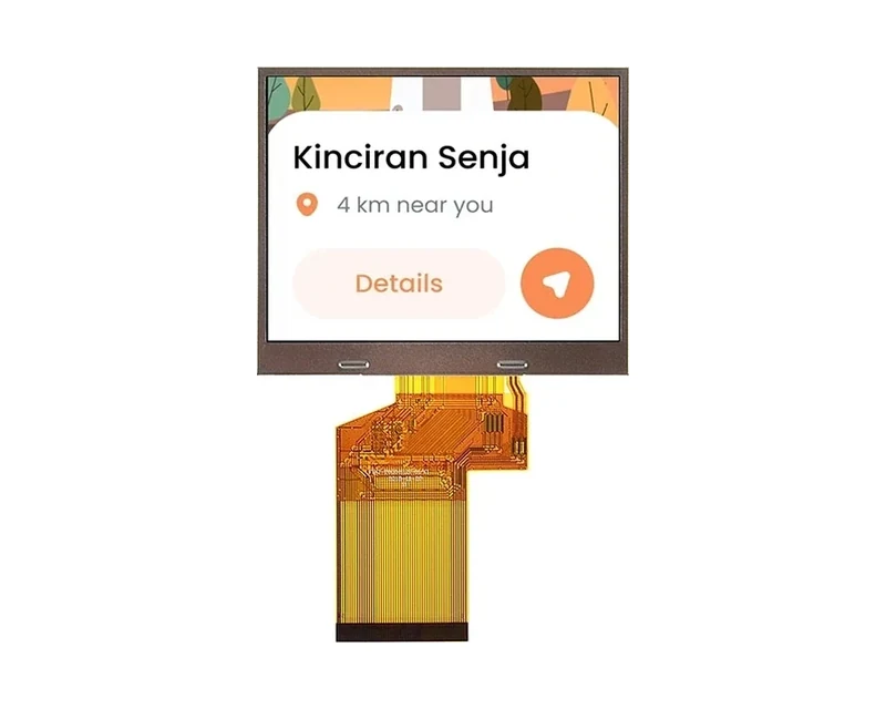
RG-T035HLSWA-01
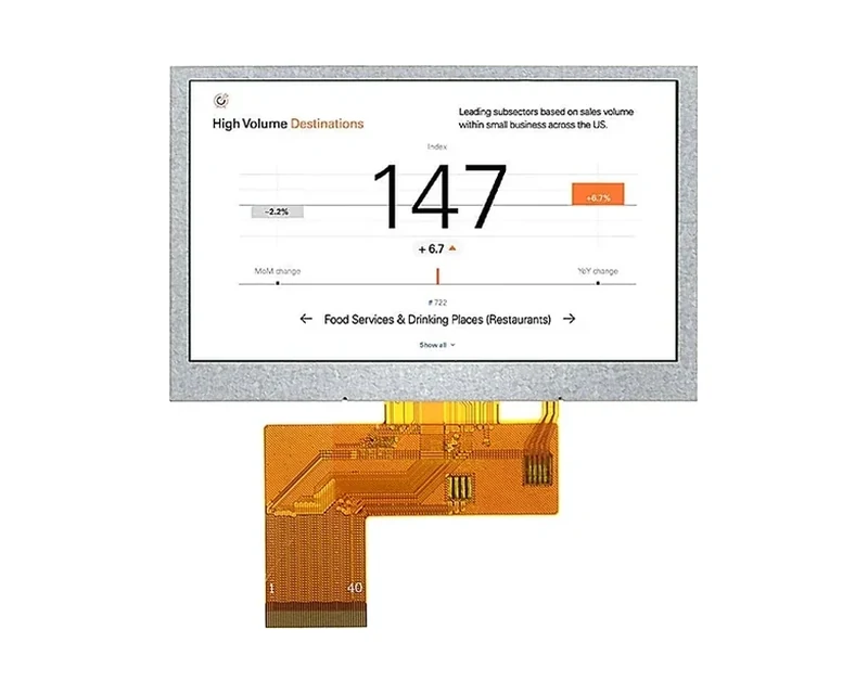
RG-T043BPSWA-02
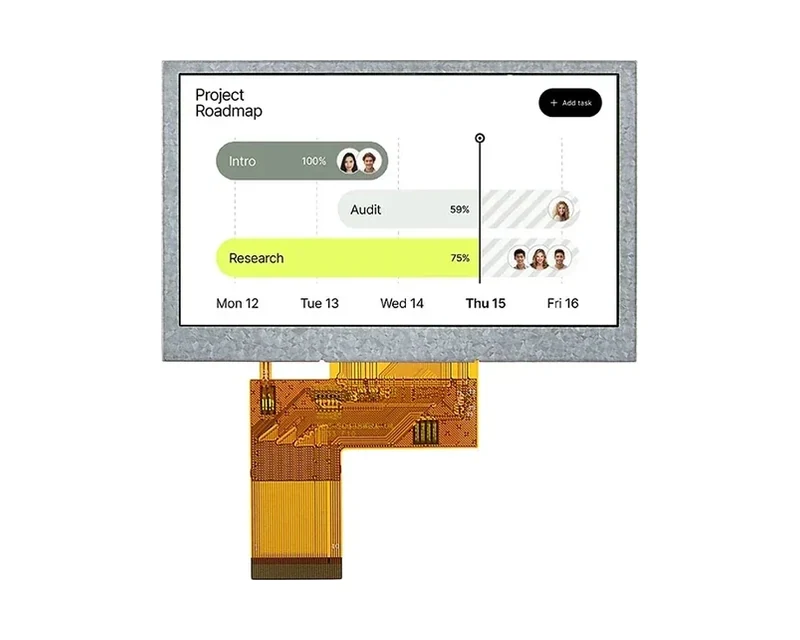
RG-T043BWSWA-02
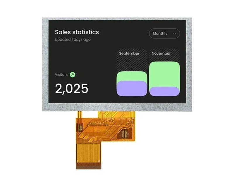
RG-T050BWSWA-02

RG-T050BWSWA-02CP

RG-T050BWSWA-02CA
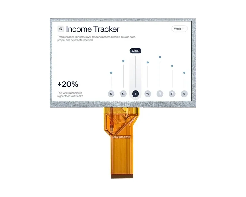
RG-T070QWHW-01
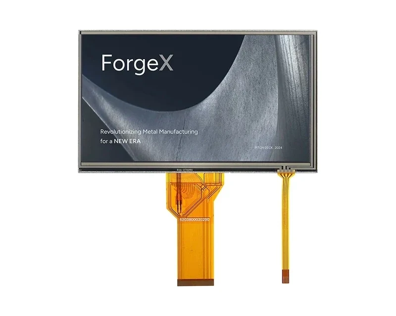
RG-T070QWHW-01P
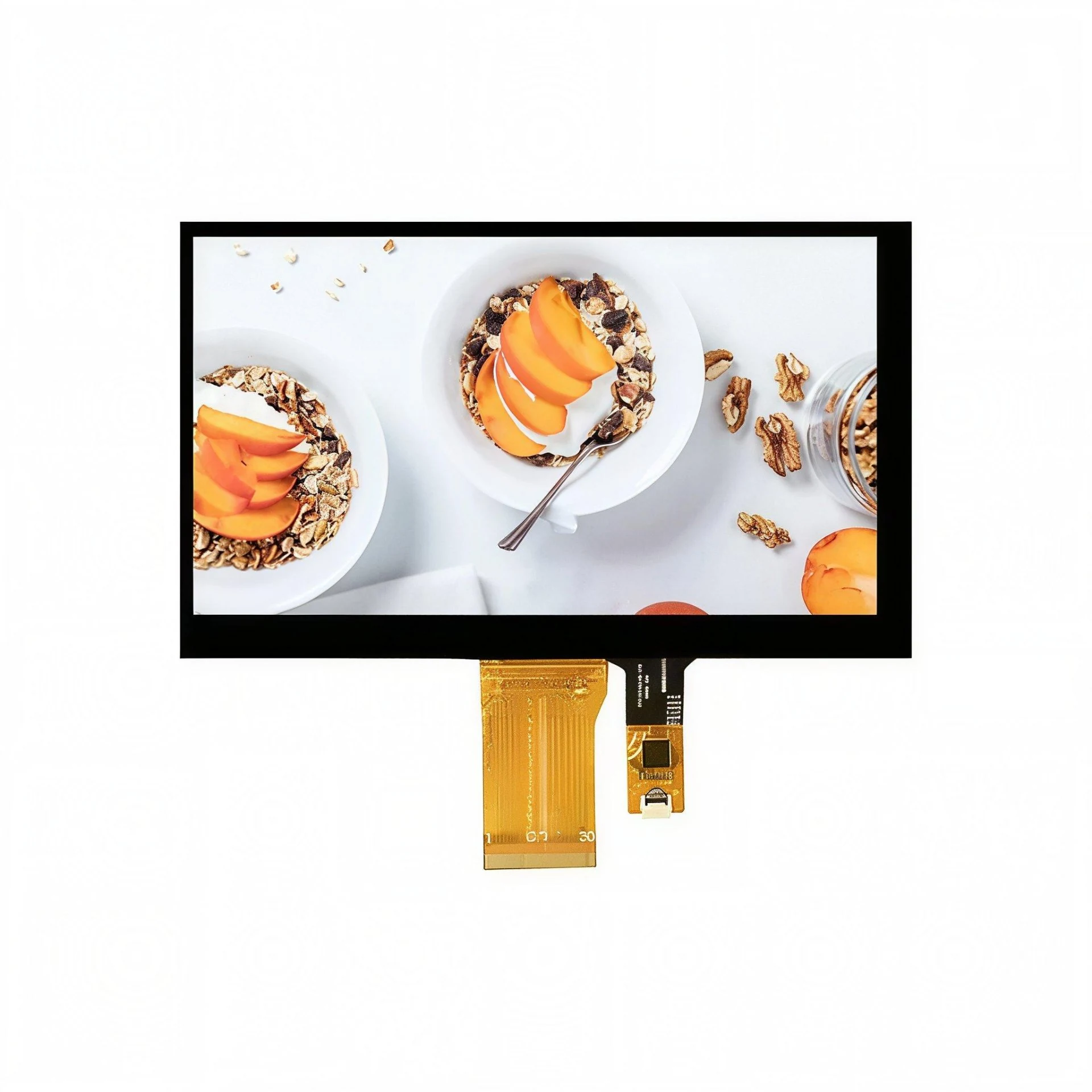
RG-T070QWHW-01CA
RG-T070QWHW-02
RG-T070QWHW-02P
RG-T070QWHW-02CA
RG-T070QWHW-03CA

RG-T070SWHWA-01

RG-T070SWHWA-02

RG-T080BXEWA-01
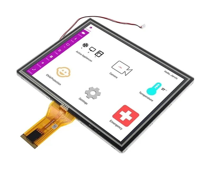
RG-T080BXEA-01CP
RG-T084BXJWA-01
RG-T101BYEA-01ND
RG-T101HIEWA-01
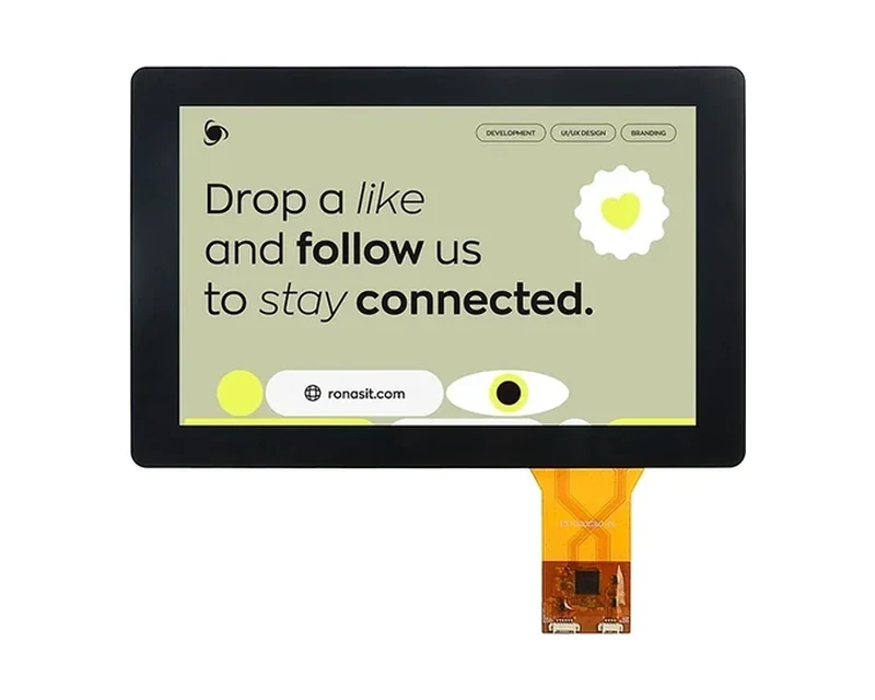
RG-T101HIEWA-01CP

RG-T101HIEWA-03
RG-T101HIEWA-04
RG-T121QXHA-02
RG-T156QFHWA-01
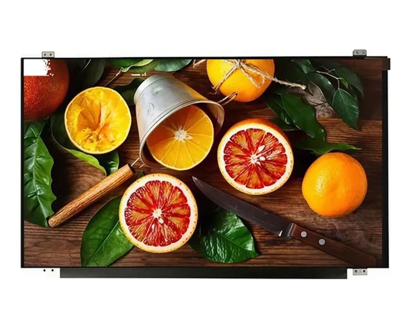
RG-T156BFHWA-02
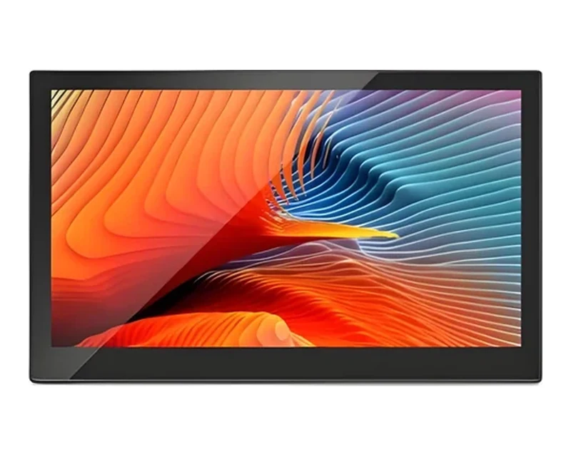
RG-T156BFHWA-02CP
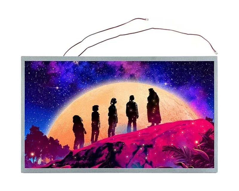
RG-T185BFHWA-02
Can’t find the exact model you need?
This is a standard model, and our online catalog shows only part of what we build. We hold additional models not listed here, and we can adjust brightness, interface, touch or outline within an existing product family, or evaluate a fully custom solution. If this model does not fully match your requirements, please email your specifications to sales@odmlcd.com. We’ll help you identify the right part or assess a custom option.
FAQ
Do you supply displays for railway applications?
Yes. Our wide-temperature line (−30 to +80/+85 °C) is used in door indicators, cab auxiliary displays and trackside HMI. We design to railway-grade practices — vibration-tolerant mounting, locking connectors and conformal coating options — and support your qualification process with design files and test documentation. Send us your specification and we will confirm fit once the project scope is confirmed.
Can you maintain supply across a 10-year vehicle program?
Yes. Standard modules are produced continuously (not project-by-project), and we commit to long-term supply with pin-compatible successors if a panel is ever revised. See our Business Terms for the full supply and EOL policy.
What operating temperature range does a railway display need?
Inside a heated cab or saloon, −20 to +70 °C usually covers the enclosure. An unheated trackside cabinet needs −30 °C or lower at the cold end. Of the 33 modules on this page, 29 are rated from −30 °C and 15 reach +85 °C; the four parts specified to +70 °C are the compact in-cab types, and they are marked as such in the specification table.
Do railway displays need to be sunlight readable?
A driver's desk display faces low sun through the windscreen, and a door indicator can sit behind a tinted window, so both benefit from 700 cd/m² or more. A saloon PIS panel that is never in direct sun does not, and paying for brightness there only adds heat and backlight current. Choose luminance per position, using the position table above rather than one figure for the whole train.
Can you provide EN 50155 or EN 45545 documentation?
We supply module-level datasheets, drawings, material declarations and test reports that feed your qualification file. The equipment type approval is held by the system integrator, and we do not represent a bare display module as certified equipment. Tell us the class you are qualifying to and we will confirm which ratings carry margin against it.
Do you offer capacitive touch for railway HMIs?
Yes — nine of the 33 modules ship with a bonded capacitive panel and two with resistive. For gloved operation a resistive panel or a capacitive controller tuned for gloves is usually the safer choice; for public ticket machines, capacitive behind anti-vandal glass is the common arrangement. Bonding method matters more than the touch technology at cold temperatures.
How do you handle condensation inside the display?
Two measures: optical bonding removes the air gap where moisture condenses, and a conformal coating protects the driver board if the enclosure seal is imperfect. A desiccant or breathable membrane in the housing handles the residual moisture. Condensation is the failure mode least visible on a datasheet and the most common in unheated cabinets, so it is worth naming explicitly in your specification.
What if none of the 33 modules fits my position?
The same panel families can be re-configured around a different backlight stack, a bonded touch panel, a longer FPC or a different connector, and a fully custom module is possible where the volume supports it. Send the position, the environmental envelope and the interface you are designing around, and we will come back with the nearest catalogue part plus the delta.
Related reading: railway display requirements, vibration and shock testing for TFT modules, and wide-temperature display design.