
Industrial HMI Display Modules — 7″ to 15.6″ Touch TFT | RONEN
Human–machine interfaces live in dusty cabinets, on vibrating machines and next to motors that heat the panel. RONEN builds 24 HMI-grade TFT modules from 7.0″ to 15.6″ with resistive (RTP), capacitive (CTP), 800x480–1920x1080 resolution and 250–1000 cd/m² brightness, backed by 5+ year supply continuity from our ISO 9001:2015 factory. Pick a standard model below or let us stock FPC, backlight and cover lens.
- 24 touch modules, 7.0″–15.6″ — CTP for sleek fronts, RTP for gloves
- RGB / LVDS / MIPI interfaces matched to common HMI SoCs
- Long-life LED backlight, wide-temperature options, Standard models
The Cabinet Is 15 °C Hotter Than the Room
A panel mounted in a control cabinet lives in a different climate from the plant around it. The drive, the power supply and the panel’s own backlight all dissipate inside the same enclosure, and with no forced air the internal air settles 10–20 °C above the hall. That is the temperature the panel actually sees, and it is the one that should be compared against the operating range — not the thermostat on the wall.
The consequence is not usually a dead panel; it is a slow one. Liquid-crystal response time lengthens as temperature rises toward the upper limit, contrast falls, and the backlight derates if the LED heatsink is inside the same pocket of still air. For a cabinet design, three measures cost little: leave a vent path top-to-bottom rather than side-to-side so convection runs, keep the panel away from the drive’s heatsink, and mount the panel’s metal frame to the cabinet wall so the enclosure acts as a heatsink.
RTP or CTP: The Glove Question Comes First
Most HMI touch decisions are argued on appearance and settled by gloves. The functional split:
| Resistive (RTP) | Capacitive (CTP) | |
|---|---|---|
| Input | Pressure from finger, glove, or any stylus | Conductive contact — bare finger, capacitive stylus, or a glove designed for touch |
| Multi-touch | None (single point) | 10-point typical |
| Front surface | Soft top film, scratches over time | Glass or hard-coated film, survives cleaning |
| Optics | Air gap adds reflection and slight haze | Can be bonded — image sits on the glass |
| Wet or oily hands | Tolerant | Tolerant if tuned; water films can cause false points |
The decision rule that survives contact with a factory: if the operator wears thick nitrile, leather or heat-resistant gloves and the process cannot tolerate a missed press, specify resistive. If the panel is cleaned with solvents, seen by customers, or needs pinch and zoom, specify capacitive and tune it for the glove the operators actually wear — a controller tuned on a bare finger will feel dead through 1.5 mm of leather.
Panel Cut-outs, Mounting Torque and Vibration
An HMI front panel is a mechanical joint as much as an electrical one. Three failure modes account for most field complaints, and all three are decided at the drawing stage:
- Cut-out tolerance. The module’s bezel covers a few millimetres around the active area. If the cut-out is at the top of its tolerance and the bezel at the bottom of its own, a bright edge shows through. Specify the cut-out from the module drawing and check the stack-up, rather than deriving it from the active area.
- Clamping force. Even pressure on the gasket seals the front; uneven screw torque distorts the frame and shows as a pressure mura (a light patch) in the corner nearest the tightest screw. A torque specification and a sequence are part of the assembly document.
- Vibration. A panel bolted to a vibrating machine sees the frame flex; the FPC bond and the connector are the parts that fatigue. A short service loop in the flex, and a connector with a locking bar, cost almost nothing and remove the most common intermittent fault.
EMI From the Drive Next Door
The panel is usually the least noisy thing in an industrial cabinet, and the most exposed. A variable-frequency drive switching at 4–16 kHz, or a servo amplifier, couples into the display harness; the symptoms are a shimmering image, a horizontal band that tracks motor load, or a touch panel that reports phantom points when a specific axis moves.
Counter-measures, in order of cost: route the display cable away from the motor cable and cross at right angles where they must meet; use a shielded LVDS pair with the shield grounded at the panel end; add a common-mode choke at the panel connector; and only then consider a different interface. A 300 mm RGB ribbon is an antenna; the same signals as two LVDS pairs in a shielded jacket are not.
Resolution, Viewing Distance and the 7-Inch Default
HMI panels are read from 30 cm to a metre, and the resolution question is really a question about the smallest element on the screen. The numbers in this family:
| Diagonal | Resolution | Pixel density | Pixel pitch |
|---|---|---|---|
| 7.0″ | 800×480 | 133 PPI | 0.19 mm pixel pitch |
| 7.0″ | 1024×600 | 170 PPI | 0.15 mm pixel pitch |
| 8.0″ | 800×480 | 117 PPI | 0.22 mm pixel pitch |
| 10.1″ | 1024×600 | 118 PPI | 0.22 mm pixel pitch |
| 10.1″ | 1280×800 | 149 PPI | 0.17 mm pixel pitch |
| 15.6″ | 1920×1080 | 141 PPI | 0.18 mm pixel pitch |
At arm’s length, 800×480 on 7.0″ is 133 PPI — enough for 12 px labels and large numeric readouts, marginal for dense parameter tables. 1024×600 on the same diagonal gives 170 PPI and is the better default for anything with more than about six rows of text. On a 15.6″ panel at a metre, 1920×1080 is comfortable and 1366×768 would be adequate; resolution above that buys nothing the operator can resolve.
The Range at a Glance
| Size | Models | Resolutions in this range | Panel / touch variants | Where it usually goes |
|---|---|---|---|---|
| 7.0″ | 16 | 800×480, 1024×600 | TN 13 / IPS 3 | Compact machine panel |
| 8.0″ | 2 | 800×600, 1024×768 | TN 1 / IPS 1 | Machine panel |
| 10.1″ | 5 | 1024×600, 1280×800 | IPS 4 / TN 1 | Standard HMI |
| 15.6″ | 1 | 1920×1080 | IPS 1 | Line panel, control room |
Standard Modules in This Range
24 standard models in this family
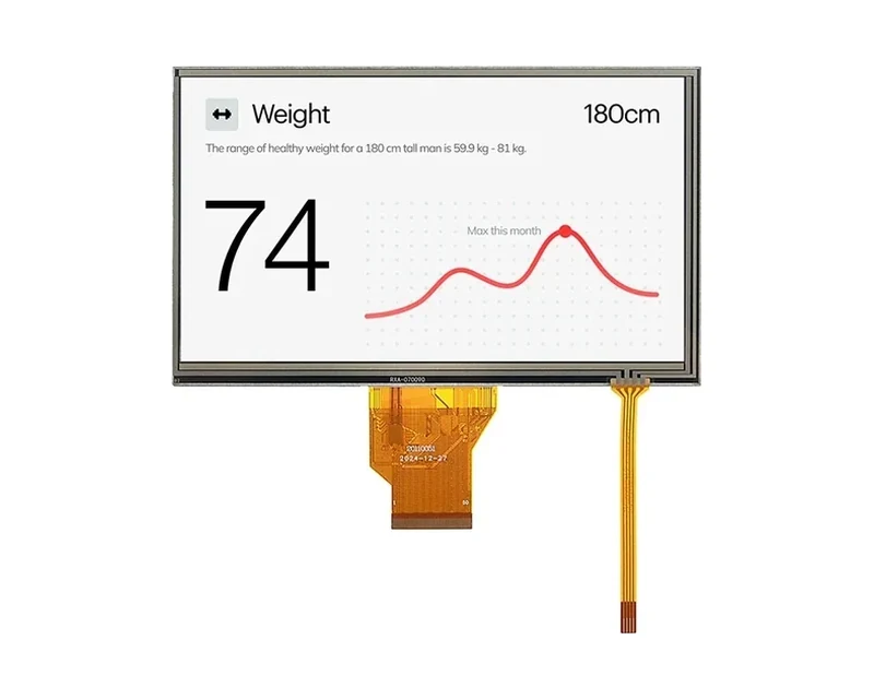
RG-T070QWE-01PD
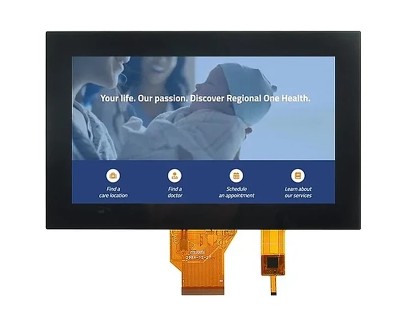
RG-T070QWE-01AD
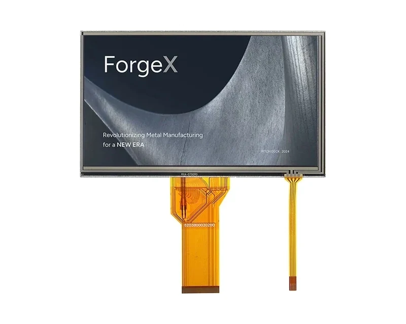
RG-T070QWHW-01P
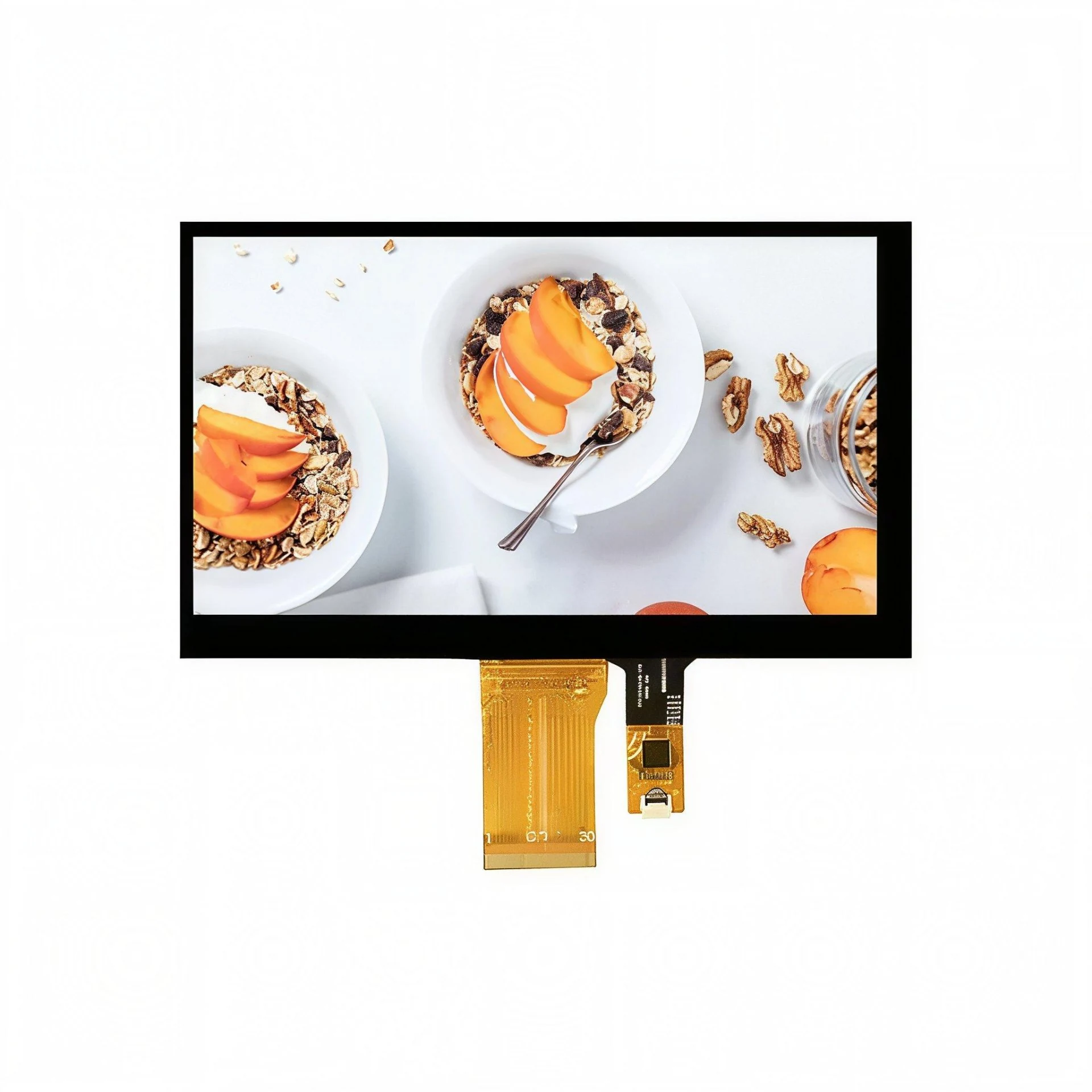
RG-T070QWHW-01CA
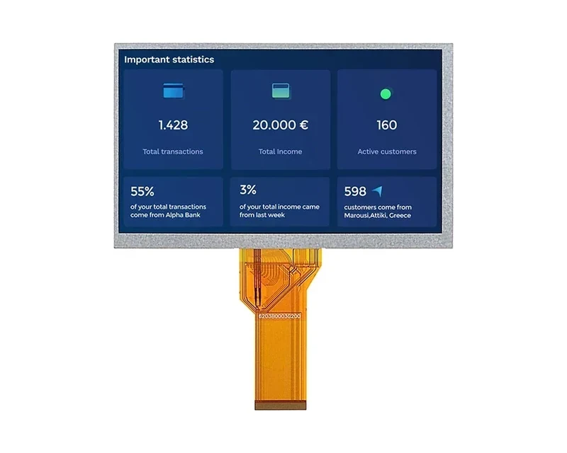
RG-T070QWHW-02
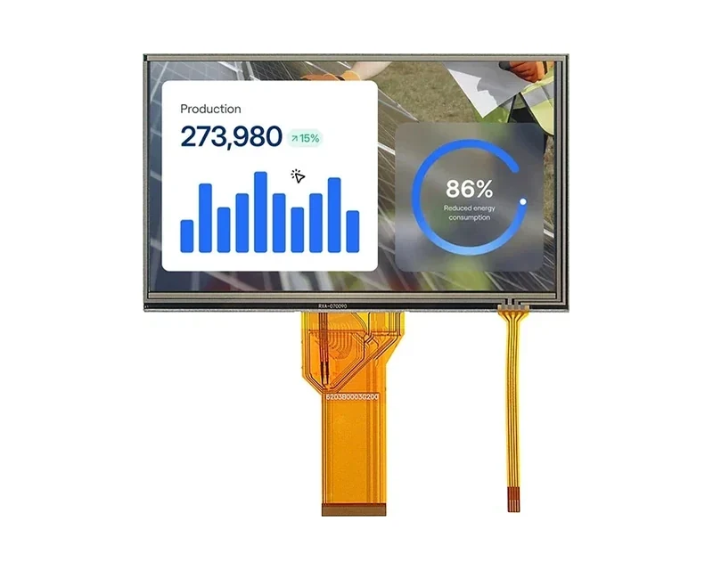
RG-T070QWHW-02P
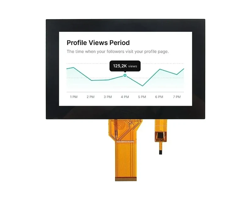
RG-T070QWHW-02CA
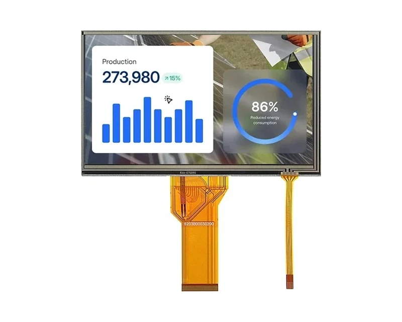
RG-T070QWHW-03CA
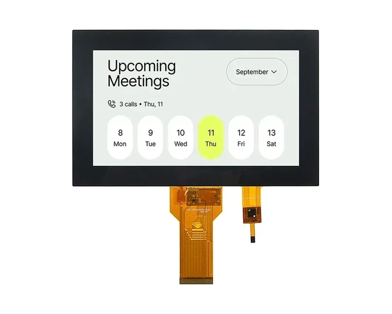
RG-T070KWSA-01CA
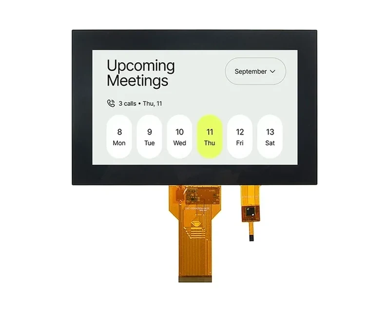
RG-T070KWSA-01CP
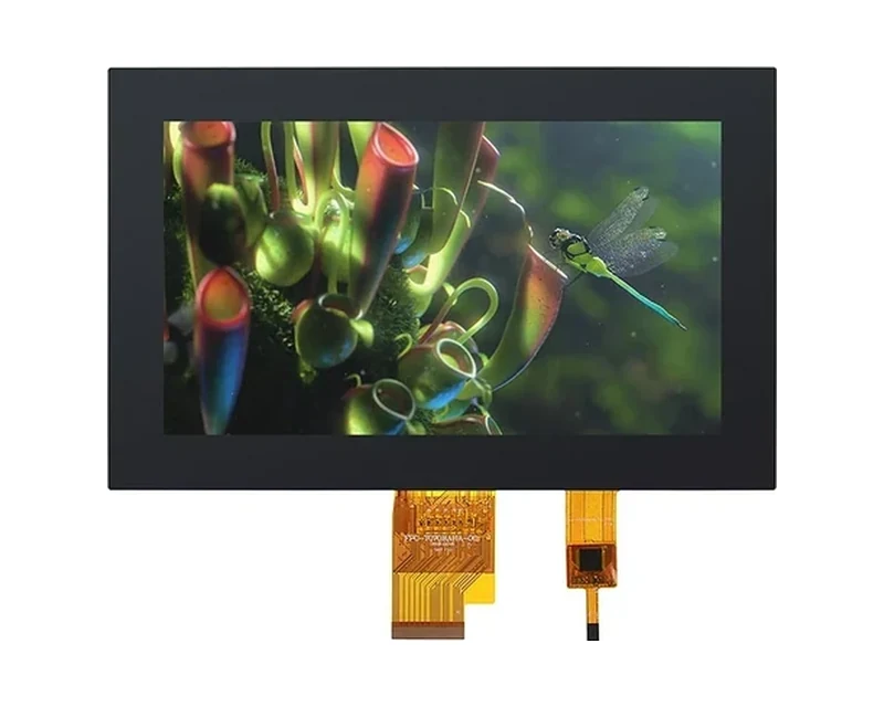
RG-T070BAHA-01CA
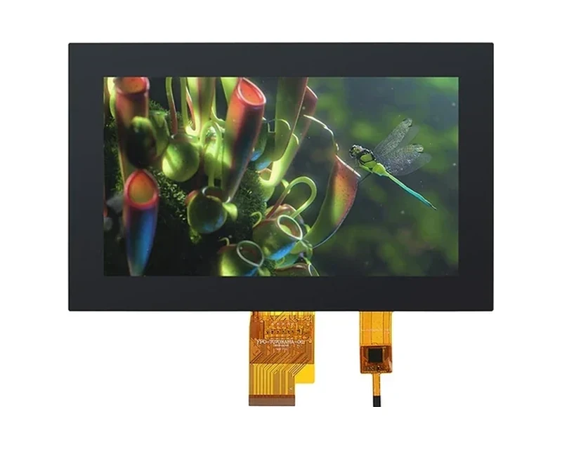
RG-T070BAHA-01CP
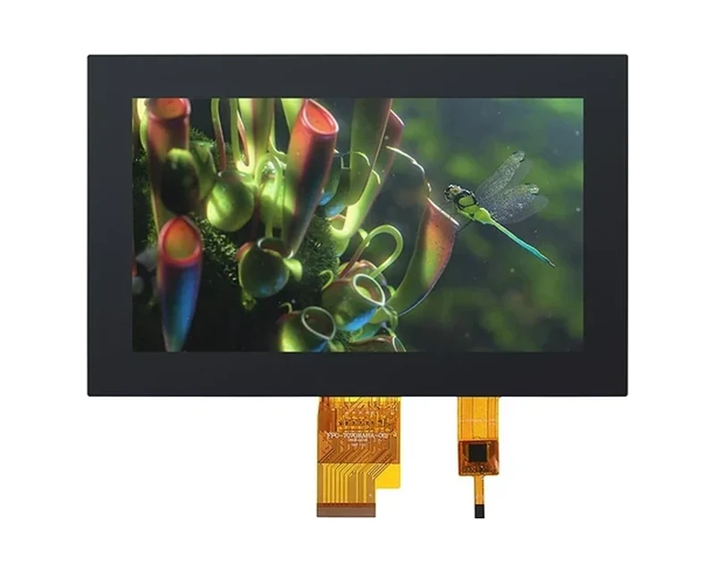
RG-T070BAHA-03P
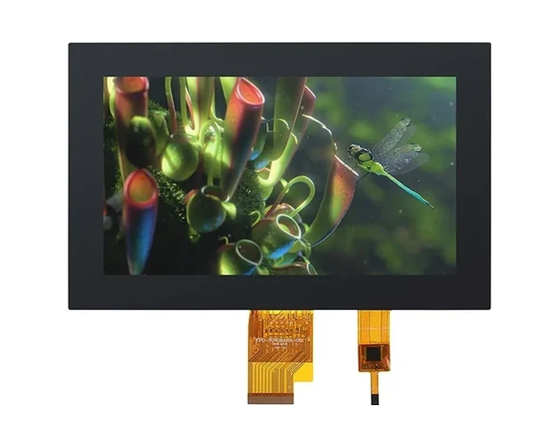
RG-T070BAHA-03CA
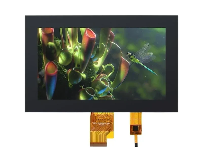
RG-T070BAHA-03CP
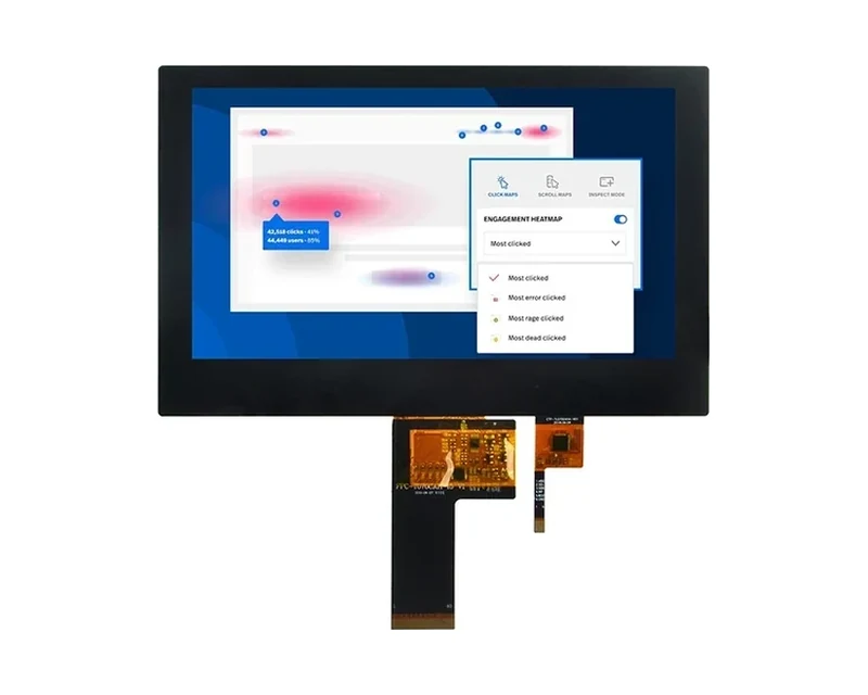
RG-T070BAHA-19CA
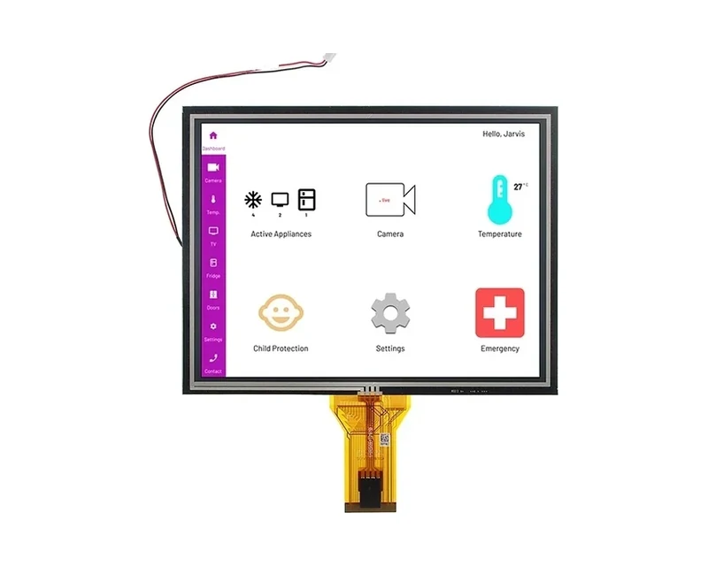
RG-T080QGH-07P
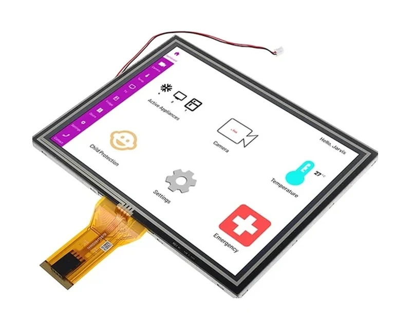
RG-T080BXEA-01CP
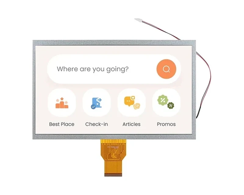
RG-T101BAE-01PD

RG-T101BAHA-02CP
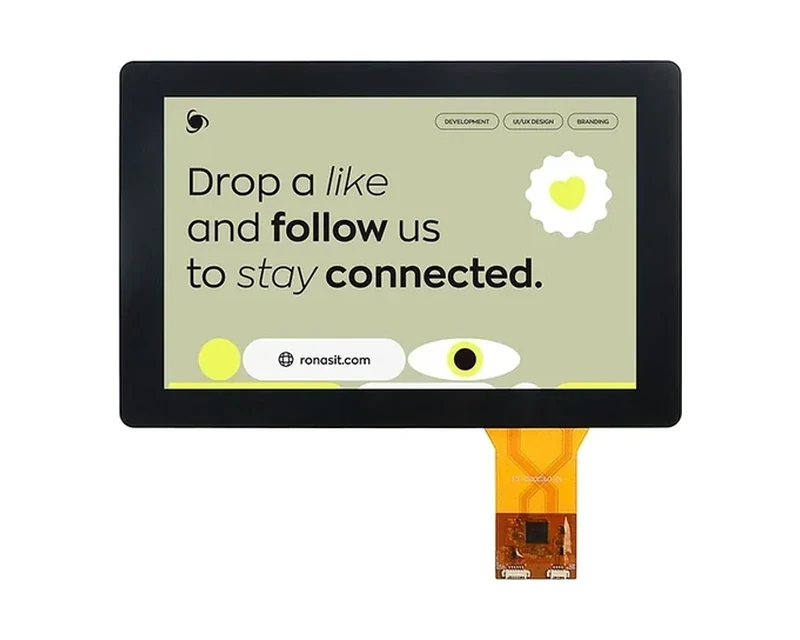
RG-T101HIEWA-01CP
RG-T101QIHA-01CA-B
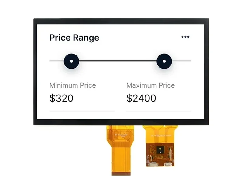
RG-T101BAHA-02CD
RG-T156BFHWA-02CP
Can’t find the exact model you need?
This is a standard model, and our online catalog shows only part of what we build. We hold additional models not listed here, and we can adjust brightness, interface, touch or outline within an existing product family, or evaluate a fully custom solution. If this model does not fully match your requirements, please email your specifications to sales@odmlcd.com. We’ll help you identify the right part or assess a custom option.
FAQ
Is the touch responsive?
Our PCAP line (36 standard models) supports 10-point multi-touch, glove and wet-hand operation, with ≥100 Hz sampling rate. Controllers are selected for industrial EMI environments and can be tuned for the thickness / cover-lens stack-up.
What display interfaces do your TFT modules support?
RONEN's 190+ model catalog spans the common industrial interfaces: RGB, LVDS, MIPI-DSI, SPI and 8080/6800 MCU (parallel). The exact interface for each model is listed on its product page, so you can match it to your controller without guessing.
If your board needs a different signaling or an adapter, our ODM team can re-layout the FPC or supply a bridge board — see the standard catalog modules page.
Browse the full list on the products page.
How do you handle long-term supply and end-of-life (EOL)?
The 190+ standard models are produced continuously rather than project-by-project, backed by our own 35.3M+ pcs/year capacity, so steady multi-year supply is the default. For automotive and medical programs this is reinforced by IATF 16949 (incl. product design, Ch. 8.3) and ISO 13485 certifications.
We operate a PCN / EOL notification process and support last-time-buy planning. Request the formal obsolescence and long-term-supply policy for your program on the contact page.
What are the order quantities and stock?
All 190+ standard models are held in our standard program, so you can order exactly the quantity your build needs, from prototype runs to volume production. Custom / ODM builds are quoted case by case (typically 10–500 pcs) with volume-based pricing — tell us your volume and we'll quote.
What internal temperature should I design the cabinet for?
Measure it rather than assume it. In a sealed cabinet with a drive and a power supply, internal air commonly sits 10–20 °C above the hall, and the panel surface adds several degrees more once its backlight has run for an hour. Design against the measured panel-environment temperature with margin, and remember that a +70 °C ambient rating is not the same as a +70 °C panel temperature.
Does capacitive touch work through work gloves?
Through thin gloves, usually, once the controller is tuned for that stack. Through thick leather or nitrile it becomes unreliable, because the glove’s capacitance and thickness attenuate the finger signal. If operators keep gloves on all shift and every press must register, resistive is the lower-risk choice; a capacitive panel tuned for the glove is workable where multi-touch is worth the trade.
Why does my panel show a light patch near one corner?
That is pressure mura — mechanical stress on the panel from uneven clamping. It appears when one screw is tightened harder than the others, or when the gasket is thicker on one side. Fix it with a torque specification and a diagonal tightening sequence, and check that the cut-out has clearance rather than pressing on the panel frame.
What causes horizontal bands that change with motor load?
Almost always conducted or radiated noise from a drive or servo amplifier coupling into the display harness. Shorten and separate the display cable, cross motor cables at right angles, ground the LVDS shield at the panel end, and add a common-mode choke at the connector. Changing the panel rarely fixes it — the noise is entering the cable, not the glass.
Is 800×480 still acceptable for a new HMI design?
For a panel showing large numbers, bar graphs and a handful of labels at arm’s length, yes — 133 PPI at 7.0″ is legible and the part is cheaper and brighter per watt. It stops being adequate when the UI shows parameter tables, trends with fine gridlines, or dense multilingual text. In that case step to 1024×600, which is the same diagonal and the same enclosure.